In this article:
- Prerequisites
- Data Collection
- Data Segmentation
- Building Model
- Model Performance & Live Classification
In industrial environments, different machine operation behaviors can be detected using machine learning models in conjunction with various sensors – for example, the operational condition of a machine may be monitored using an IMU sensor, and the machine’s vibration signature, responding when the machine deviates from normal operation, or when a specific fault condition is encountered. Similarly, a machine’s operational condition may be detected using its motor’s current signature.
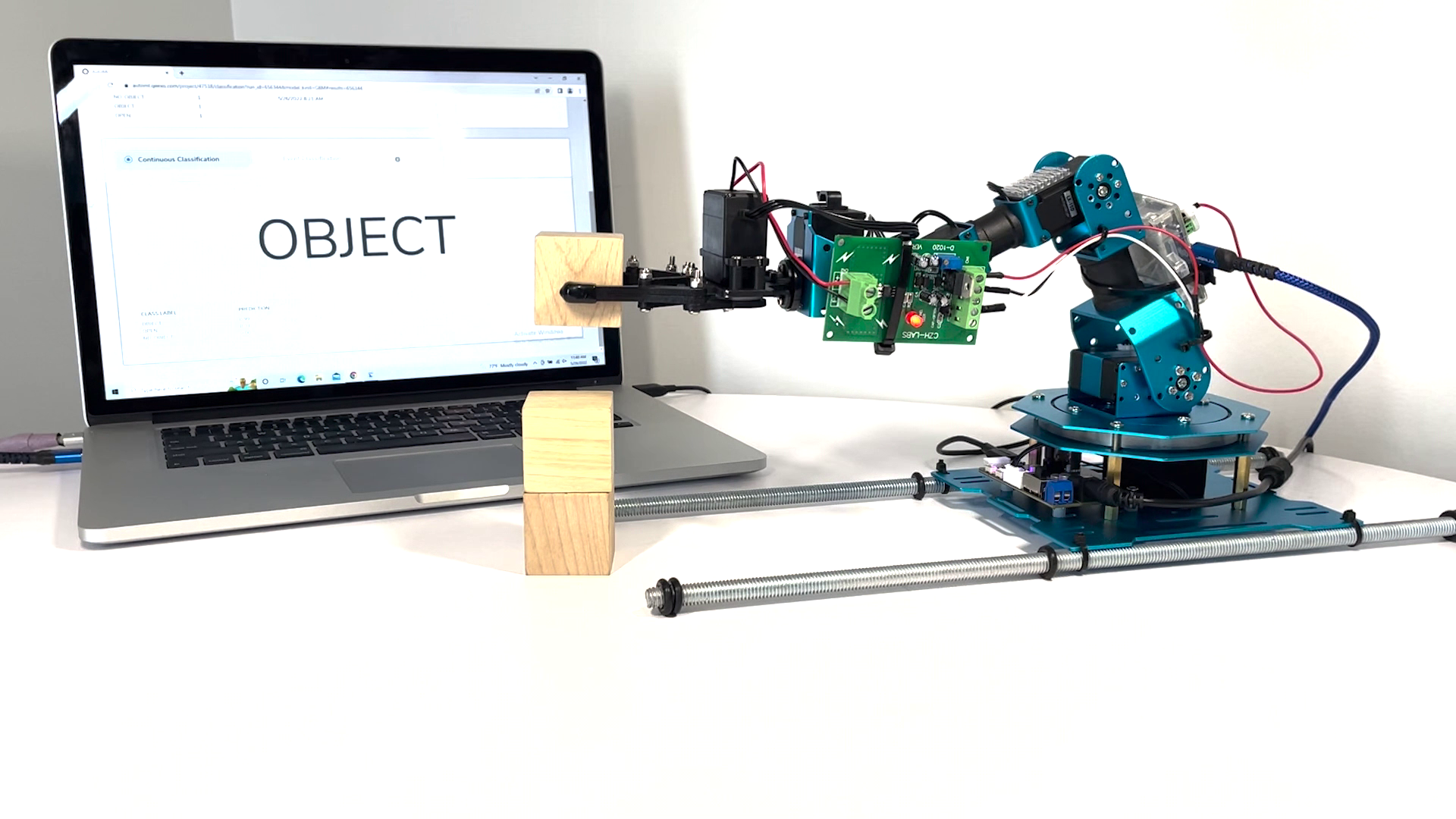
Assuming we are operating a smart warehouse optimized for an e-commerce company. In the warehouse, we employ several, “intelligent robots mover” to help us to move objects from spot to spot. In this demonstration, we have used a miniaturized, “intelligent robots mover” powered by Qeexo AutoML to determine whether the robot griped an object.
This blog is intended to show you how to use Qeexo AutoML to build your own, “intelligent robots mover” from end to end, including data collection, data segmentation, model training and evaluation, and live testing.
Please enjoy! ????
Prerequisites
- Robot Arm
- Sensors
- Wires
- Male to male jumper wires to connect the STWIN to the current sensor
- Either multi-strand or solid core wire to connect the current sensor to the motor
- Soldering iron and solder wire
Set Up
- Robot arm assembly video guide
- Connect the current sensor
- Remove the cover from the gripper motor by unscrewing the four screws securing it to the body of the motor.
- Put back the screws after removing the cover. This ensures that the motors’ gears do not get misaligned

- Connecting the current sensor to gripper motor
- When you remove the motor cover, you will see a red color wire within the purple squared area, which looks similar to the wire in the blue squared area on the image below. De-solder the red color wire you find in purple squared area.

- Cut a piece of red wire from previously purchased wires. Connect one side of wire to ‘IP+’ terminal on the current sensor module (shown as circle 1 in the image below), then solder the other side of the red wire to the motor (shown as circle 2 in the image below).

- Cut a piece of black wire from previously purchased wires. Connect one side of wire to ‘IP-’ terminal on the current sensor module (shown as circle 1 in the image below), then solder the other side of the black wire to the PCB next to the motor (shown as circle 2 in the image below).

- While other combination of connections are possible, its best if we stick to a common convention across our demo setups to ensure consistency in the data we collected.
- Connecting current sensor to STWIN
- Connect current sensor with the STWIN sensor
- Connect STWIN with laptop device

Data Collection
- Create a project with STWIN (MCU) with multi-class classification
- Collecting data
- Click ‘Collect training data’ on ‘data’ page.

- Step 1 – Create new environment
- We assigned ‘office’ as the name of the new environment as data is collected from our office.

- Step 2 – Sensor configuration
- Make sure to build an environment containing ONLY the current sensor with value of 1850 Hz.

- Step 3 – Collect 2 datasets

- What data to collect?
- We are building a multi-class with 3 classes including ‘open’, ‘object’ and ‘no_object’. This model is meant to detect the gesture of the gripper and whether there is an object gripper gripped.
- There are 2 datasets we collected:

- Collection label: OBJECT
Duration: 600 seconds
We collected 600 seconds data of the gripper repeatedly grip a wood block and release it - Collection label: NO_OBJ
Duration: 600 seconds
We collected 600 second data of the gripper repeatedly grip and release without an object. - Below is a screenshot of what each of the datasets look like:


Data Segmentation
Before we segment the data, it is necessary that we understand the data. Below is a zoom in of the two datasets annotated with their respective classes, this is how we intend to segment our data:
- OBJECT
For dataset “OBJECT”, we segment the data into 2 classes and labeled them as “OPEN” (blue color areas) and “OBJECT“ (yellow color areas).
- NO_OBJ
For dataset “NO_OBJ”, we segment the data into 2 classes and labeled them as “OPEN” (blue color areas) and “NO_OBJECT” (red color areas).
Building Model
- We are selecting the 2 datasets we mentioned above with their segmentation.
- We selected “Automatic Sensor and Feature Group Selection”. By selecting Automatic Selection, Qeexo AutoML will evaluate different combinations of features and choose the best performing feature group for you.

- For “Inference Settings”, we Enter Manually and set the “INSTANCE LENGTH” value as 2,000ms and “CLASSIFICATION INTERVAL” as 200ms.
A Classification Interval of 200ms means that the software will make a prediction once every 200ms. Where an Instance Length of 2,000ms means the software will use 2,000ms of incoming data to make the prediction. We set Instance Length to 2,000 ms because the gripper takes about 2 seconds to finish each movement (for example opening and closing). By making the Instance Length big enough, we are making sure it covers the whole movement in a classification.
- Lastly, we selected two algorithms to train which are “Gradient Boosting Machine (GBM)” and “Random Forest (RF)”. Note that we have previously selected all available algorithms on the platform, and these two are the best in terms of the time taken to train a model, sizes and latency.

Model Performance & Live Classification
Model Performance
Below is a summary of our chosen models’ performance. We flashed GBM to hardware for live classification.

Live Classification
- Push GBM to hardware by clicking the arrow button under “PUSH TO HARDWARE” to flash the model to STWin.
- Click Live test
- Operate grippers
- Watch a video of the demo at this link.
Conclusion
From the image under ‘Model Performance’ section, we can see that with AutoML’s sensor and feature selection enabled, we landed with two good performing, high accuracy machine learning models.
Finally, we will flash the compiled binary back to the sensor (aka, the STWIN) and use AutoML’s live classification feature to check if the classifier is producing the expected output. As shown in the video, the final model is performing very well and can accurately recognize whether the robot has an object in within gripper.